Each combustion of organic substances produces particles, which are discharged with the flue gas. These particles, called fly ash, fly through the boiler with the flue gas and settle down on the inner boiler walls and the heat exchanger tubes of the boiler. This results in a reduction of the heat transfer. These contaminants are removed by means of various cleaning systems. The most important automatic online cleaning methods are described below.
Typical residue balance of a waste incineration plant
Nowadays, coal-fired power plants are being successively taken out of operation due to the negative environmental impact, therefore the considerations in this blog refer to waste incineration plants.
Heat transfer surfaces of incineration plants for municipal waste, industrial waste, sewage sludge or biomass are affected by boiler fouling due to ash deposits and corrosion of steel parts. In biomass plants for pure biomass only the deposits are problematic, whereas plants for treated wood are additionally attacked by corrosion from the paints and coatings. The causes of boiler fouling and the cleaning methods practiced are basically applicable to all types of combustion technology.
Boiler fouling is basically caused by
- Deposits of solid particles
- Deposits of not yet solidified particles
- Condensation of various substances directly on the colder surfaces
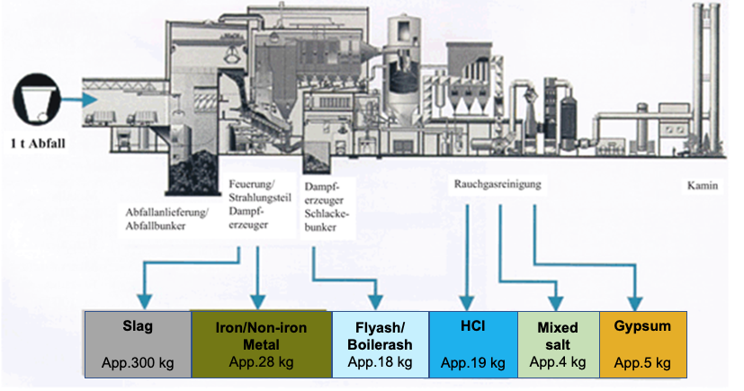
Fig. 1: Typical residue balance of a waste incineration plant (Springer Verlag)
In the mass balance of residues from a typical waste incineration plant it can be seen that from one ton of fuel (waste) about 300 kg of rather unproblematic slag and about 18 kg of fly ash are produced, which are separated to a predominant part of 13 kg in the process stages downstream of the boiler. Approximately 5 kg of fly ash (named as boiler ash) is deposited in the boiler, which must be continuously removed during the plant operation by means of suitable cleaning procedures.
The challenge
In addition to solid mineral slags, the incineration of organic substances also produces flue gas with a small proportion of fly ash, which is discharged with the flue gas. The condition of the fly ash changes with the decreasing flue gas temperatures. A typical temperature profile of the flue gas between the combustion chamber and the boiler outlet for a clean and a «normally fouled» boiler is shown in the following graph.
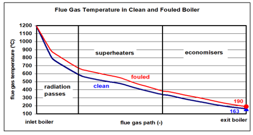
Fig. 2: Typical temperature profile of the waste gas in the waste incineration boiler [HZI Archive].
At temperatures between 1200°C and approx. 750°C various particles are in a melted/doughy form. They settle down near the rather colder boiler walls. The subsequent adhesion process leads to growth, compacting and solidification of the transported particles. Such caking is responsible for poor heat transfer and must be avoided as far as possible by the geometry of the combustion chamber and the flow of the hot flue gas. We speak of caking, which partly adheres in the form of a stony mass. Such can usually only be removed mechanically after cooling down of the boiler. The heavy metals are in the gas phase at the high temperatures and escape with the flue gas.
In the downstream boiler sections is the exhaust gas successively cooled. The fly ash settles on the heat transfer surfaces and causes fouling, possibly also blockages or adhesions in the flue gas path. In addition, the heavy metals condense more and more as the flue gas temperature drops, causing corrosion.
Fly ash is an inhomogeneous mixture of macroscopically visible particles with different colours. These consist mainly of silicates and the oxides, sulfates, carbonates, sulfides as well as chlorides of various metals. The particle size varies from 20 µm to over 7 mm with a maximum between 300 and 800 µm. Remarkable are the black particles, consisting of macromolecular carbon [R. Bechtler, Forschungszentrum Karlsruhe]. The picture taken under the microscope shows a typical structure of the particles. The fly ashes are hygroscopic. Extensive stalactites can also be formed with the humidity of the exhaust gas.
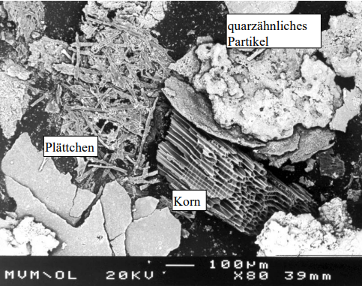
Fig. 3: Screen fraction 300 to 800 µm, [TU Karlsruhe, L. Birnbaum, U. Richers, W. Köppel].
In the chemical composition, there are sometimes significant systematic differences. This applies (in particular) to the flow direction. On the upstream sides, the deposits contain considerably more chloride and as well more calcium than on the downstream sides. The heavy metals lead and zinc are present in higher quantities on the downstream sides [Harpen CUTEC Clausthal 2006]. At flue gas temperatures between approx. 550°C and 200°C practically no corrosion by chlorides occurs.
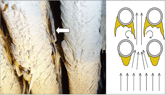
Fig. 4: Deposits on a superheater, where a deposit is growing from a rear tube to the front. Next to it is a sketch with the flow shape assumed to be the cause. [VGB Project “Instationary Deposit Behaviour” 2005]
A comparison of the deposits of the upstream and downstream sides shows that:
- more chlorine, sodium and potassium are present on the upstream side and
- more aluminium and silicon as well as lead and zinc are found on the downstream side.
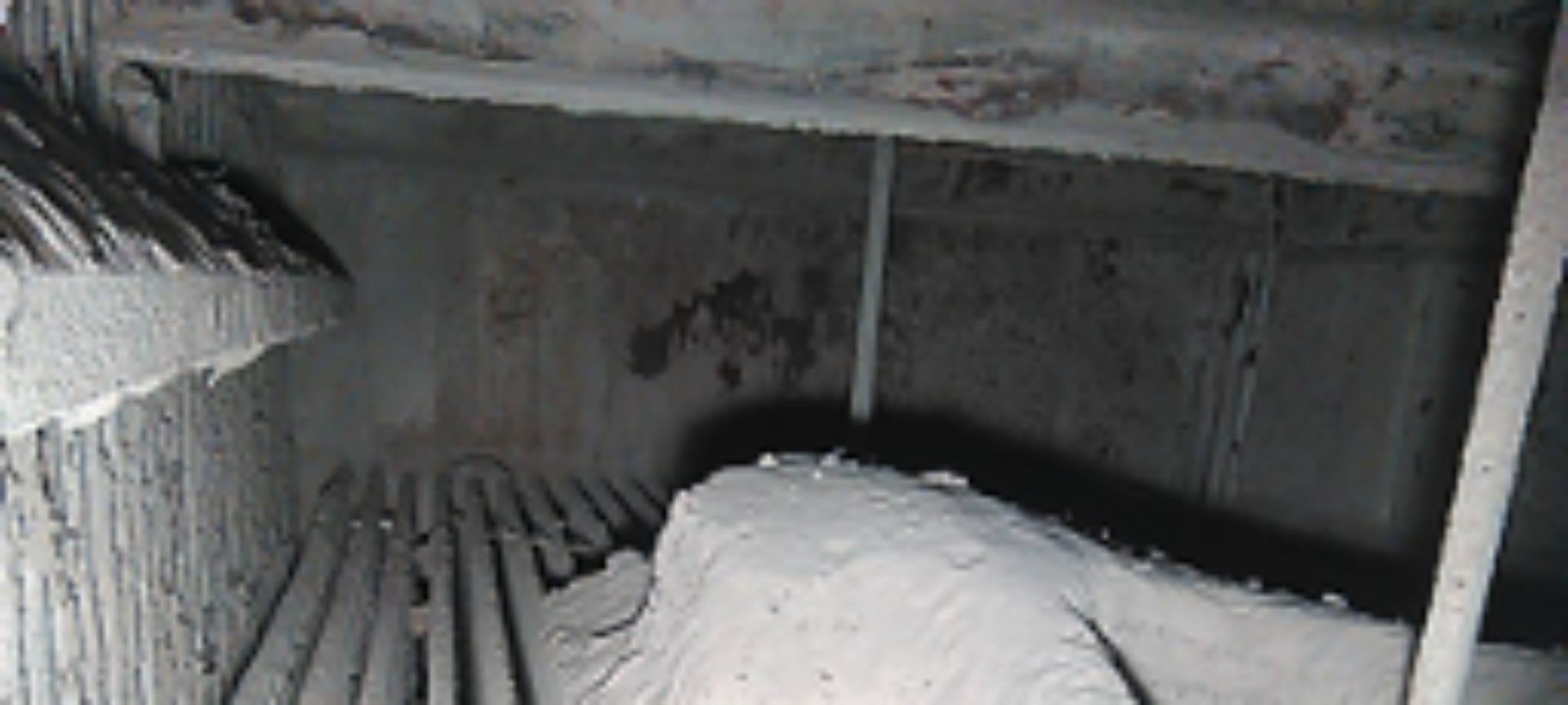
Until the deposits do not compact due to their composition and local temperatures, they tend to remain loose. As time goes by, some layers will detach themselves and fall off. The remaining layers significantly lower the heat transfer and must be removed as soon as possible.
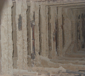
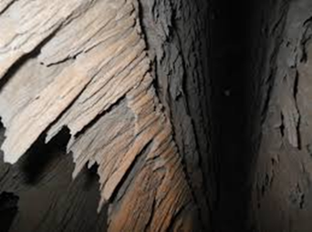
Fig. 5: Examples of boiler fouling by loose deposits
The effective heat conduction of a coating is composed of heat conduction through the solid bridges, heat conduction of the medium filling the pores, convective heat transport with the medium and radiation from pore wall to pore wall. Since the pores are very small, convection and radiation play practically no role. Since the thermal conductivity of solids is about a factor of 100 higher than that of gases, the dominant mechanism is heat conduction through the solid bridges. [VGB Project “Instationary Deposit Behaviour” 2005]
The approaches
No general classification of boiler fouling has been established in science and technology as far. Systems are available on the market to determine the thickness of the fouling locally on the tubes or boiler walls during operation. Alternatively, online balancing systems are known which – by comparing the clean and fouled condition – provide comparable contamination indicators for the heating surfaces. Many operators have extensive practical experience and operate boiler cleaning intervals only based on their own empirical data of boiler behaviour.
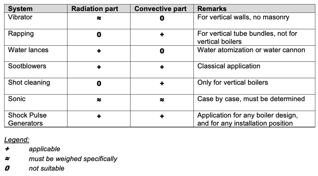
Cleaning systems for the heating surfaces
The fouling structure and thus the compactness of the deposits play an essential role in the application of the cleaning system.
The aim of all efforts must be to identify the primary factors leading to slagging and fouling and to take appropriate countermeasures. Secondary measures include all procedures for cleaning the heating surfaces during operation or when the plant is shut down.
In the following we will concentrate on the online procedures which are automatically activated during plant operation without the need for operating personnel and without opening the boiler internals containing flue gas.
Basics of the listed cleaning systems have already been described in the following blogs: