High fly ash load in the flue gas of waste and biomass incineration boilers causes deposits on the tube bundle heat exhange surfaces. To meet the boiler efficiency and to maintain the required temperatures of the downstream located plant components, the tube bundles must be cleaned periodically. In order to achieve the most constant possible conditions and for safety reasons, the cleaning should be carried out online during the boiler operation and without any personal intervention in the boiler. The cleaning procedures practiced in the plants are described below.
The heating surfaces should be kept free of deposits as far as possible so that the efficiency of the boiler does not deteriorate. For waste or biomass boilers, a proper cleaning of the heating surfaces is particularly important because of the high fly ash content of the flue gas. In the following, procedures are described which do not require any personal intervention for maintaining a continuous boiler operation. Such automatic online cleaning processes can be activated by a programmed local control system or from the central control system of the entire plant. The wear and tear or, derived from this, the service life and the extent of maintenance of both the heat exchanger surfaces and the cleaning equipment, together with their operating material costs, are of decisive importance for the economic operation of the thermal treatment plant.

Note: For cleaning of the radiation sections see a separate blog at https://www.explosionpower.ch/en/top-five-cleaning-technologies-to-control-buildups-in-radiation-passes/
Graphic of Explosion Power GmbH
Mechanical rapping units
In mechanical rapping cleaning, the adhering contaminants are removed from the heating surfaces by causing them to vibrate. For this purpose, the pipes must be suspended elastically. The oscillations of the tube bundles are caused by hammers being struck at certain points or bolts. The hammer, or a pneumatic knocker, can strike onto the lower manifold or a stop point of an elbow. The boiler wall passage is usually executed with a stuffing box and must be kept tight.
Rappers with falling hammers are slowly rotated by an electric motor.
As a rule, one impact is triggered per bolt at intervals of two hours each, resulting in a total of about five minutes cycle (respectively one revolution of the shaft) per pass.
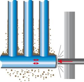
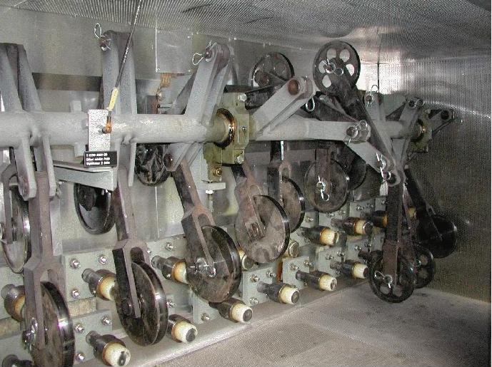
Fig 2: Principle and design of a mechanical rapping unit (example)
Rappers with pneumatic hammers (see picture below) hit the stop pins by means of compressed air-operated knockers. The rappers are either arranged as single knockers (left picture) or on a carriage (right picture), which approaches the stop pins.
The frequencies are approximately the same as for mechanical rappers. The pneumatic rappers have the advantage that sections which require more intensive cleaning can be knocked at shorter intervals. When using rapping units, wear and tear occurs at the points of the collectors to be knocked as well as at the rapping unit itself, which makes maintenance work necessary. If the wear occurs in the flue gas leading part, a repair can usually only be carried out at the next boiler shutdown. This means that the affected part of the bundle cannot be rapped until the next shutdown.
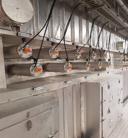
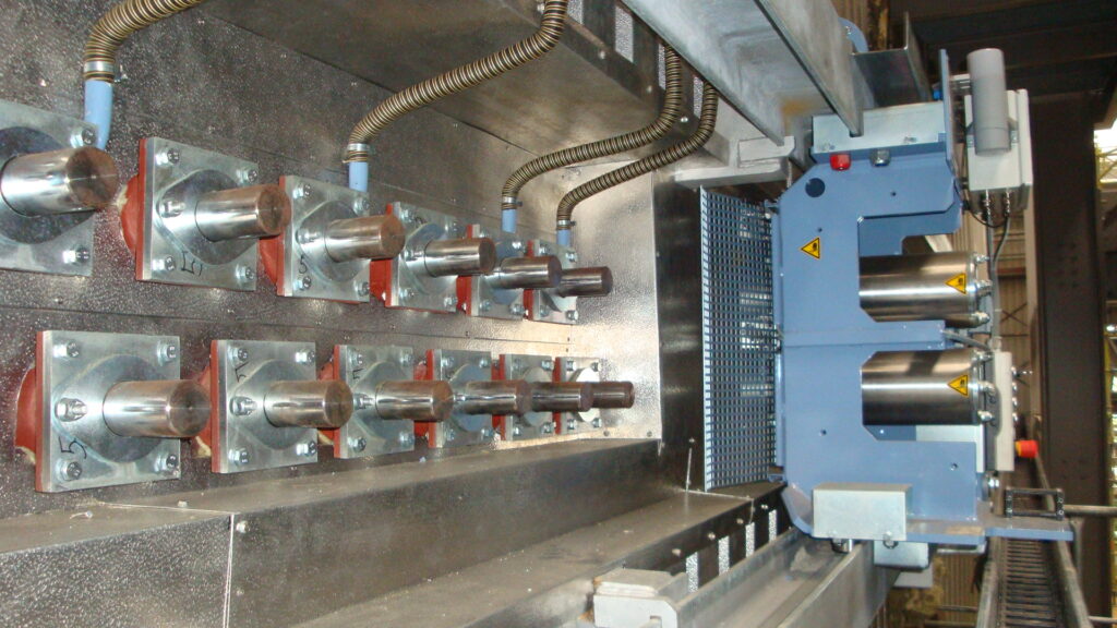
Fig.3: Pneumatic rappers as single knockers (left) and with carriage (right)
Source: Example of installations built by Hitachi Zosen Inova
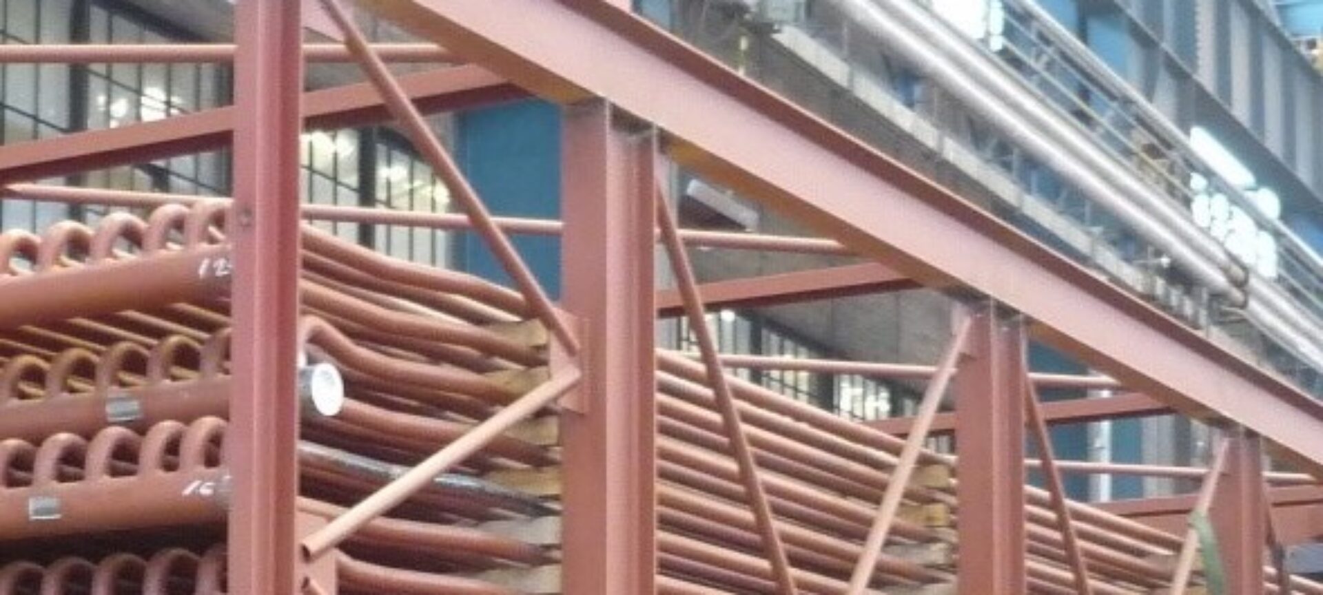
Sootblowers
By means of a jet of superheated steam (possible condensate drops due to too short or insufficient preheating can lead to severe erosion damage) or compressed air, the «soot deposits» on the heating surfaces are cleaned off by means of high relative speed of the impacted jet. The sootblowers are used either as slowly oscillating or rotating lances.
The steam is taken from the steam production of the boiler and is «lost» for the overall energy recovery by being blown into the flue gas. The corresponding amount of deionized feed water must be permanently reprocessed. The pipework and the associated condensate drainage of the steam supply line to the individual sootblowers must be carried out carefully and must be foreseen in the platform layout planning in order to minimize damage to heat exchanger surfaces by condensate.
Fly ash from waste incineration plants contain a high proportion of sharp-edged silicates and aluminum oxides, which have a very abrasive effect. Moreover, the flue gases are also corrosive. Consequently, only movable sootblowers can be used in hot flue gas areas. During the cleaning cycle, the blowpipe is periodically inserted between the heating surfaces, whereby the blowpipe rotates slowly, and the jet steam cleans the surfaces. The blowpipe is then retracted again. There must be enough space outside the boiler to store the long blowpipe outside the boiler.
In case of a possible malfunction in the cleaning process, the heat exchanger tubes can be directly damaged by the escaping steam. A cleaning process usually takes between 3 and 5 minutes and the intervals vary between 4 and 8 hours depending on requirements. As each cleaning process of a sootblower leads to a certain abrasion and erosion of the heat exchanger tubes, sootblowing processes are carried out as seldom as possible, although this does not allow the boiler to remain permanently at the best possible operating point.
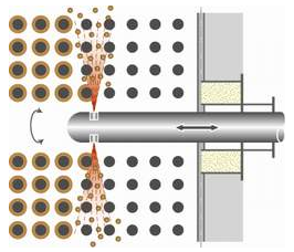
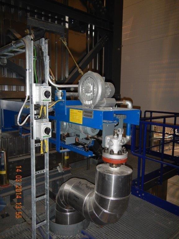
Fig. 4: Left side a principle of a movable sootblower, right side example of an executed unit
Source: Clyde Bergemann
Shot cleaning
Shot cleaning systems are only used for convective heating surfaces in vertical flue gas passes, in which the heating surfaces are arranged perpendicular to the flue gas flow and are applicable only at low flue gas and tube temperatures. The tube bundles are impinged with small metal balls and thus cleaned from deposits. During this process, approx. 200 balls of 4 to 6 mm diameter per square meter cross-section per second are distributed as evenly as possible. After discharge from the boiler hopper, the balls are separated from the ashes by a sieve. At certain types of ash, a proper separation can be difficult. The balls are returned pneumatically or mechanically to the feeding device on the boiler roof for refeeding. This can lead to severe abrasion and corresponding maintenance requirements. In order to reduce the abrasive and erosive attack on the heat exchanger tubes, protective shells or «dummy tubes» are often installed, which however, must be replaced regularly. Shot cleaning can generally cope with lower peaks of deposits than the soot blowers, therefore the cleaning process must stay permanently in operation.
Fig. 5: Principle of a shot cleaning system
Source: Left side graphics: Thomè-Kozmiensky, Thermal waste treatment, EF Verlag;
right side: execution in a plant by Messrs. Wuerz
Sonic cleaning system
Sonic cleaning with low-frequency sound waves between 70 and 270 Hz generates an acoustic pressure which propagates into the interior of the boiler. The sound waves are generated by means of compressed air acting on a membrane. Such sound waves create a spatial vibration of the boiler internals for about 20 to 30 seconds, which allows loose deposits to loosen and fall off. The field of application is usually limited to low flue gas temperatures, as the cleaning effect is mostly too low at higher temperatures and stronger caking. The interval range varies between 1 and 4 hours, depending on the requirements. Attention must be paid to a resonance superposition. The noise level as well as the vibration effect on other plant components must be considered in the design.
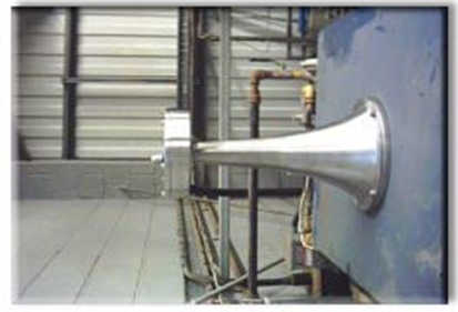
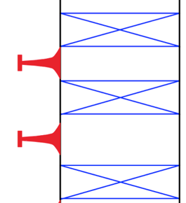
Fig. 6: Principle of a sound wave cleaning system
Source: Wikipedia, Example of execution by Prismasonics
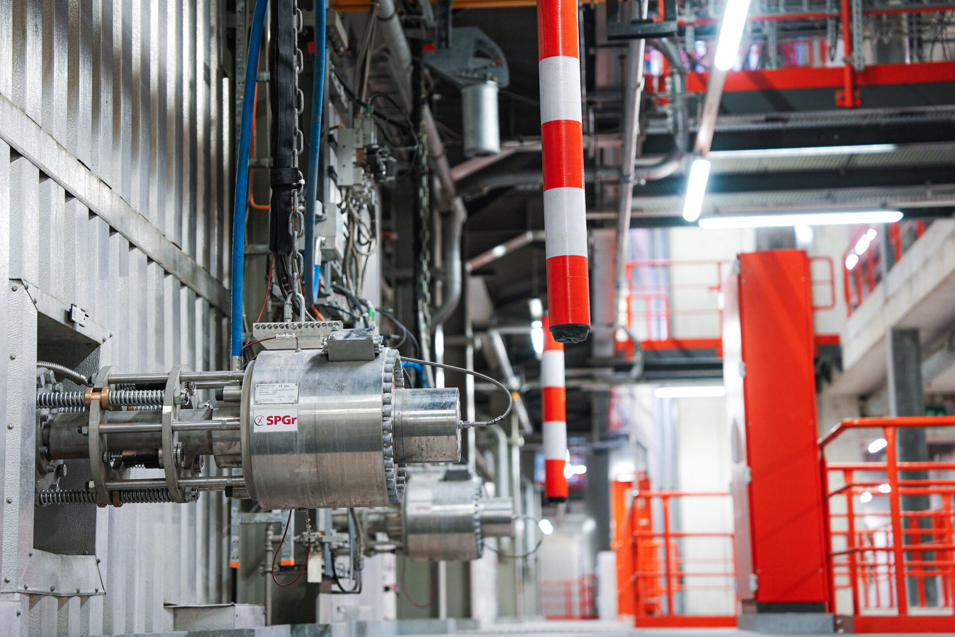
Shock Pulse Generator (SPG)
By means of isochoric combustion of a few grams of natural gas and oxygen in a pressure-resistant vessel, a small amount of combustion gas under high pressure is produced, which is suddenly let into the space between the tube bundles of the boiler. This shock wave induces a destructive sound wave in the caking, creates a brief local suction and causes a short time vibration of the ash-adhered tubes. Due to the spatial spread of this impulse, the entire interior of the boiler is cleared of deposits, even in the opposite direction to the flue gas flow. This boiler-friendly cleaning process prevents any damage to the inner boiler parts due to such cleaning processes. The pulse has a duration in the millisecond-range and the intervals between the pulses vary between 1 and 4 hours in practice, depending on requirements. The minimum shock pulse interval is 2 minutes and is periodically used during the so-called mixed operation to perform intensive cleaning phases from time to time between the normal cleaning phases. The system is as well very suitable for cleaning of finned tubes.
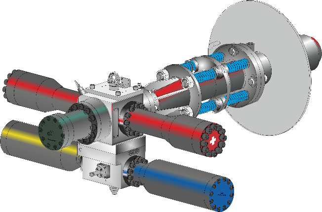
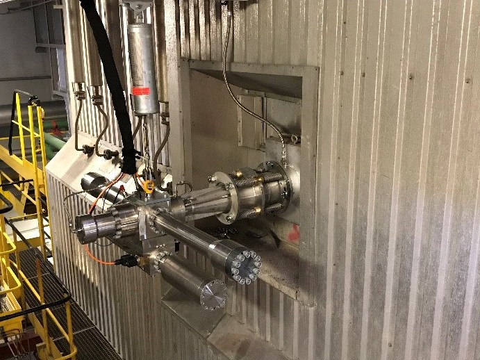
Fig. 7: Principle of the SPG, right an application in the plant
Source: Explosion Power GmbH