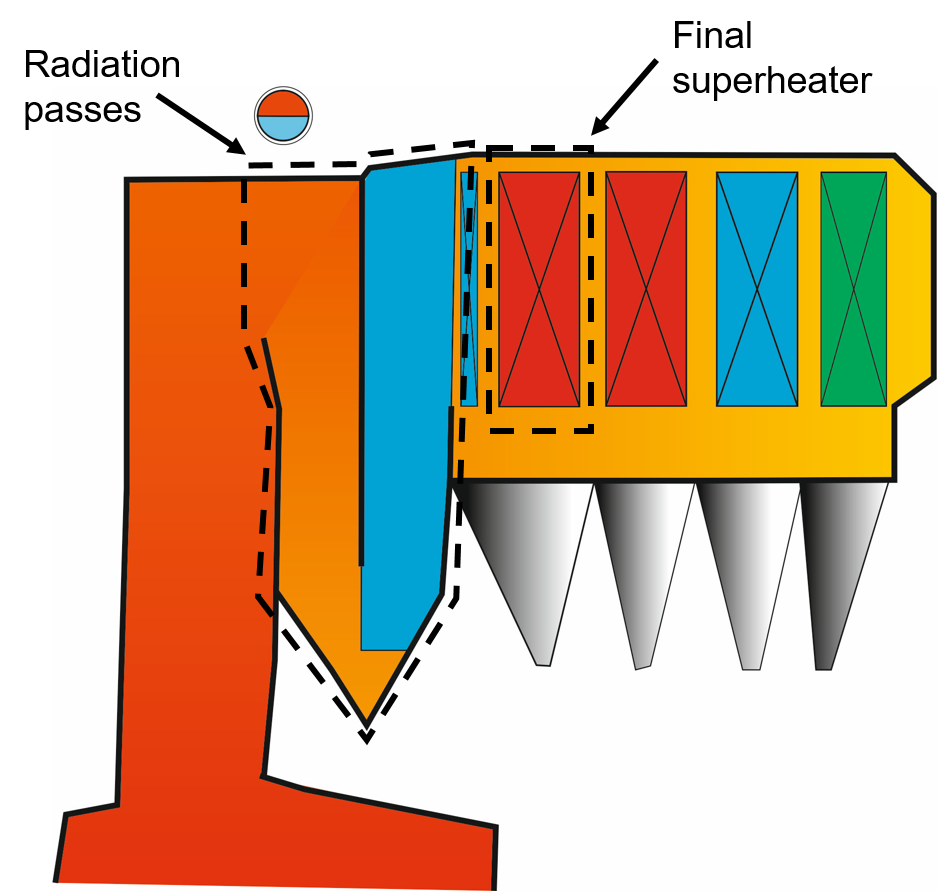
Maximal thermal efficiency with minimal corrosion – that is only attainable when the flue gases reach the final superheater at the temperature sweet spot. In other words: Cooling of the flue gases in the radiation passes must run constantly and in a controlled manner (see Figure 1). This is only possible when the buildups on the walls are controlled during ongoing boiler operation. Five technologies for the cleaning of radiation passes in waste incineration plants have established themselves: shower cleaning, water cannons and wall blowers, rapping systems and the shock pulse generator (SPG). In the following, we briefly explain the working principles behind these technologies.
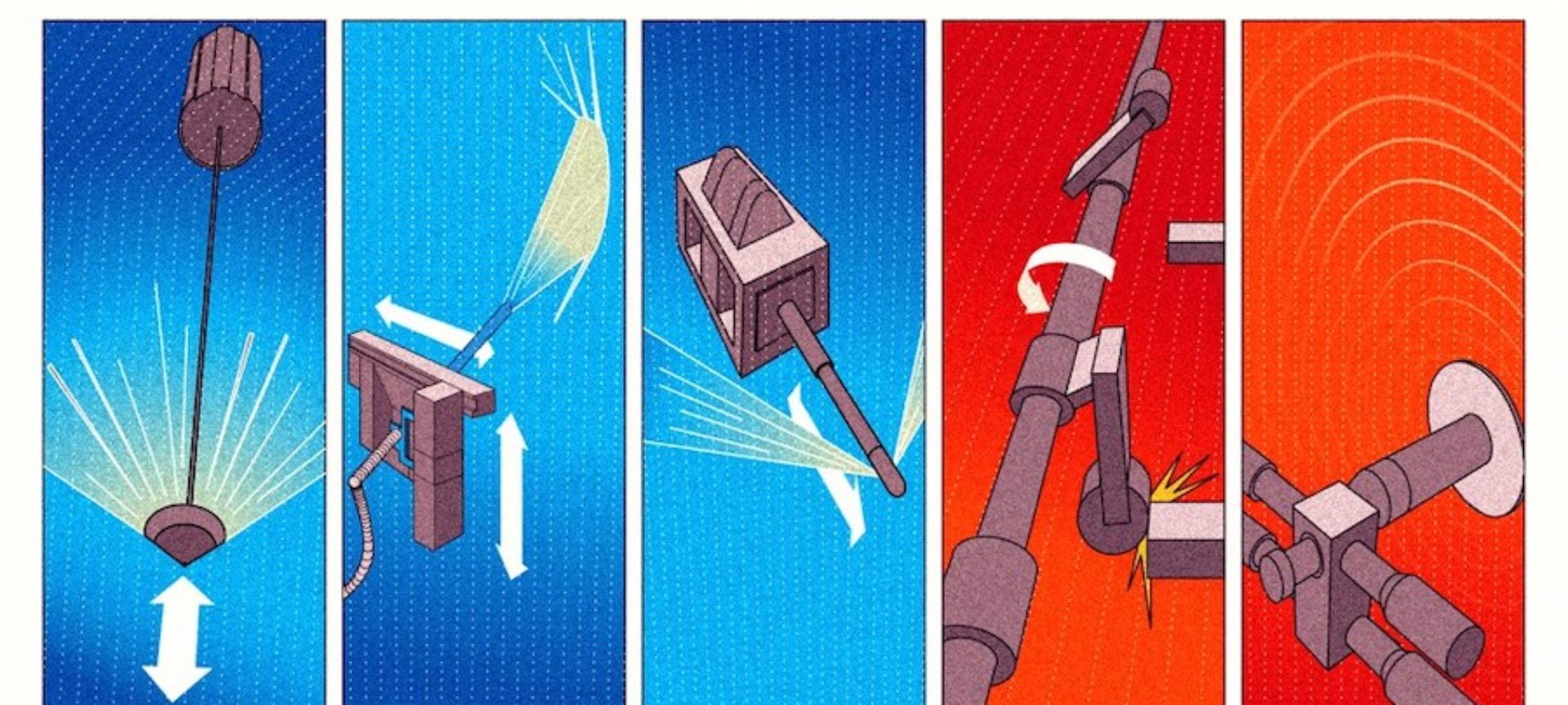
Technology 1 – Shower cleaning (shower cleaning)
Technology 2 – Water cannon (water cannon)
Water cannons are mounted on the boiler wall, resembling remote-controlled fire hoses. A lance is controlled by two servo motors and sprays a defined water jet through a nozzle onto the opposite membranes walls [1]. Almost any wall pattern can be programmed. Water canons are often controlled using heat transfer sensors or infrared cameras. Water consumption ranges between 0.8 and 1.7 kg/s. Water can flow into ash hopper in this system as well if the parameters are not set optimally.
Technology 3 – Wall blower (wall blower)
Based on the same principle as the well-known steam soot blowers, a steam or air jet is injected into the boiler through a movable lance [2]. The blowers are installed to the boiler wall and blow backwards in the direction of the membrane wall. The jet pulse dislodges the buildups. Wall blowers remain in the boiler during the cleaning cycle, and are afterwards retracted.
Technology 4 – Rapping system (rapping system)
With this technology, hammers beat the outer wall of the boiler. The buildups are dislodged by the vibrations. Pneumatic cylinders, unbalanced motors or heavy weights are used as hammers to create rotating vibrations. In contrast to shower cleaning or wall blowers, no additional media, such as water or air, is inserted into the boiler with this technique.
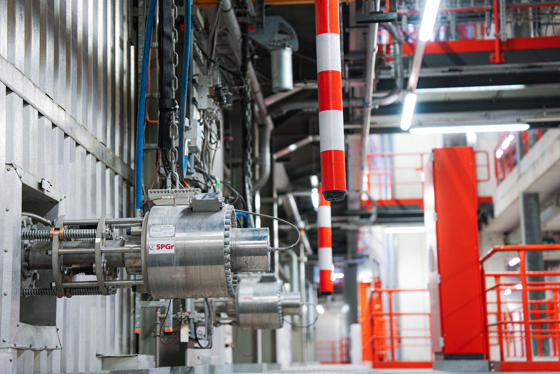
Technology 5 – Shock Pulse Generator
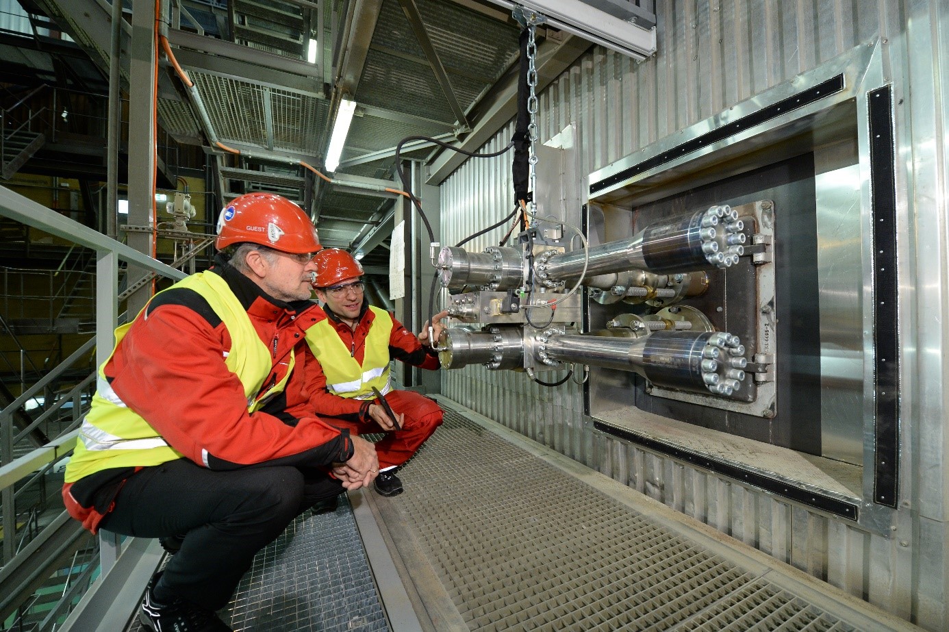
The shock pulse creates pressure waves through combustion of a mixture of gases. These cause the flue gas, boiler pipes and membrane to vibrate so powerfully that buildups drop off. The shock-like combustions that generate the pressure take place outside the boiler in a stable, pressure-proof container. As with the rapping system, here too, no foreign media is inserted into the boiler.
Why is such a system installed in your waste incineration plant?
According to a survey conducted in 2010 and 2011 [4] among 121 waste incineration plants, only 20% automatically subject the radiation passes to cleaning during ongoing operation. The reason for this is simple: There were no effective technologies available at the time they were constructed. Therefore, planners dimensioned the surfaces of the radiation passes to be so large that buildups can be accepted.
Technologies such as shower cleaning, water canons and wall blowers [2] were only available on the market at the beginning of the 21st century. Water was long the dominant cleaning medium – until the first shock pulse generators [3] went into operation in 2009. The cleaning systems listed here are the common fit-out standard for new builds today.
Bibliography
[1] Simon S.: Verlängerung der Reisezeit durch effektive Reinigung in den Leerzügen von Verbrennungsanlagen für Abfälle und Biomassen; Energie aus Abfall, Band 2, 2007, 659-672
[2] Steiner C., Ninck K.: Boiler Cleaning with Shock Pulse Generators, POWER Magazin, December 2016, Focus O&M p.18-p21, Online: http://www.powermag.com/boiler-cleaning-shock-pulse-generators/
[3] Born M, Beckmann M.: Korrosionsschutzmassnahmen in Abfallverbrennungsanlagen und Ersatzbrennstoff-Kraftwerken – Auswertung einer Betreiberbefragung, In: Energie aus Abfall 201
2, S. 393-410 http://www.vivis.de/phocadownload/Download/2012_eaa/2012_EaA_393_410_Born.pdf