
Questions & answers
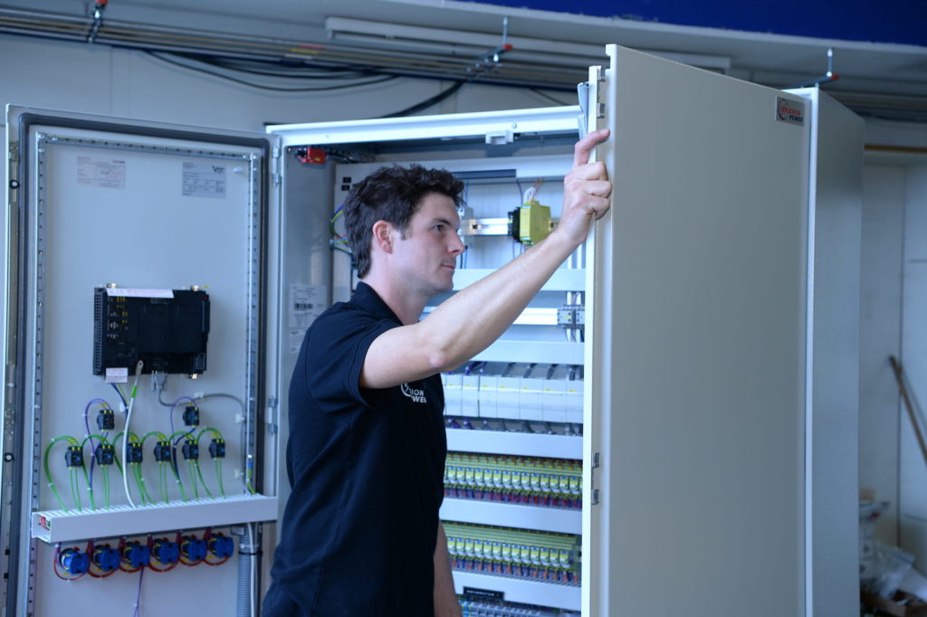
We attach great importance to the safety of the Shock Pulse Generator technology. The control of the Shock Pulse Generator is carried out by a control cabinet, which is equipped with PLC and Touch screen-Interface. In case of deviation of standard operation the generator will be shut down automatically.
Different standards are available for the signal exchange with the DCS and also with the manufacturer or the maintenance partner.
The Shock Pulse Generator system consists of:
- Shock Pulse Generators, mounted at the outside of the boiler wall on a boiler nozzle, introducing the shock pulse trough a discharge nozzle into the boiler
- Control cabinet, controlling shock pulse cycles, connected to distributed control system (DCS)
- Pressure regulating units, reducing gas cylinder pressure of natural gas/methane, air and nitrogen to 40 bar
- Valve panel, preassembly of valves, pressure transmitters and junction box
- Air Compressor Unit: supply for combustion air; integrated in SPG LogView
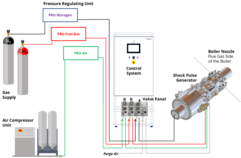
The gas supply for Shock Pulse Generators is easily carried out by means of gas cylinders or small bundles with 200 bar pressure. The pipes distributing the gas to the Shock Pulse Generators should exhibit a minimal inner diameter of 10mm and are operated at a maximum pressure of 40 bar (e.g. material V2A, nominal inner diameter DN10, nominal pressure PN63). If Natural Gas is available from the grid, a small compressor can be installed. An air compressor unit is used for the air supply. Additionally, a Nitrogen Gas Cylinder is necessary for the gas spring of the piston. The Shock Pulse Generator is mounted at the outside of the boiler wall. The discharge nozzle is introduced into the boiler by means of a boiler nozzle and is arranged flush with the inner wall of the boiler. The Shock Pulse Generator is hung movable to a crane rail and connected to the boiler flange (DN200 PN16 oder DN250 PN10) by means of a spring package. The spring package dampens the recoil towards the boiler wall. The Shock Pulse Generator can be mounted horizontally at the boiler wall or vertically at the boiler roof.
- CE-certification and EU-Conformity declaration according pressure equipment directive PED, Category II-IV (type approval module B, production approval C1)
- All parts and components are constructed high pressure resistant
- Installation of gas distribution according to local regulation
- The mixing of the flammable gas mixture is only carried out in the pressure resistant Shock Pulse Generator
- PLC controller surveys important process data and stops the Shock Pulse Generator, if a deviation from setting values occurs
- Automated, no need for operation or actions by the operating crew
- Prior to each shock pulse the alarm horn is blown and a flash light is operated
- Loudness of pulse bang outside of the boiler below 135 dB (A), short peak
- No danger to create leaks in boiler tubes because of shock pulses
- No use, transport and storage of explosives (Dynamite)
- Profibus, Modbus or hardwired (24VDC) signal exchange
Within the framework of a growing Industry 4.0 standardization, Explosion Power GmbH developed a web platform (i.e.SPGLogView) and remote access hardware (i.e.SiteManager) for the whole Shock Pulse Generator fleet. The new remote access hardware is installed as a standard for all new projects since March 2016 and is also available for all existing installations. Control cabinets equipped with a SiteManager.
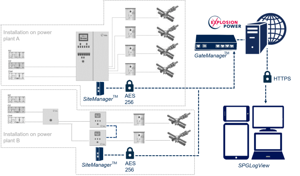
Send operational data of connected Shock Pulse Generators daily to the GateManagerTM, located at Explosion Power’s head office (see scheme above). Each SiteManagerTM communicates solely with the GateManager, to which it was linked to during the setup procedure. The operational data is made accessible to the respective customer and service partner over the SPGLogView web interface. Additionally, the control cabinet’s HMI can be accessed for remote support. The customer is asked each time for his approval, before any remote access is carried out.