
MSW Boiler Lucerne (Perlen)
Switzerland
Overview
- 2 boilers with 58 t/h steam flow per unit, since 2015.
- Capacity increase to 70 t/h in 2020 (120% of the original design)
- Boiler width 5.5 m
- 6x Shock Pulse Generator EG10L, since 01/2015 (3 per boiler), enable to maintain a constant RG temperature at the inlet to the horizontal pass, even at 70 t/h steam capacity. From July 2022 on line 1 3x SPGr10.
- 6x Shock Pulse Generator SPGr10, since 08/2021 (3 per boiler), enable to prevent strong increase of pressure drop in the horizontal pass and to achieve long travel time. Common operation with the existing rapping system.
- Plant supplier: Hitachi Zosen Inova
- Plant operator: Renergia

Planned installation from July 2022
- On Line 1, the three EG10L in the radiation pass will be replaced by three SPGr10 in June 2022
- Thereafter operation of six SPGr10
- Further optimization of cleaning performance by means of mixed mode adjustment, based on weekly analysis of boiler operating data
- Reduction of operating and maintenance costs
- Standardization of the systems with regard to operation and data exchange with PLS
- The same conversion is planned for 2023 on line 2
- The combustion air for the 12 SPGr10 is provided by an air compressor unit ACU260-80-2

3x EG10L enable low inlet temperature into horizontal pass, even after capacity increase
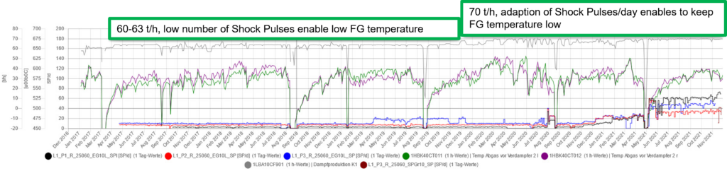
Black: Shock pulses/day of EG10L in 1st pass; Red: Shock pulses/day of EG10L in 2nd pass,
Blue: Shock pulses/day of EG10L in the 3rd pass;
Green: Flue gas temperature before EVAP2, left side; Purple: FGT before EVAP2, right side;
Gray: Life steam flow
Brown: Shock pulse/day of an SPGr10, testwise installation for comparison
Result:
The SPGs enable a low flue gas temperature at the inlet of the horizontal pass, even after the capacity increase of the boiler (measurement at inlet EVAP2-SH3, at outlet of small evaporator bundle EVAP1).
By adjusting the shock pulses/day, even lower FG temperatures could be achieved.
Additional optimizations with mixed mode operation of the SPGs are currently carried out.
Line 1: Significantly lower RG pressure drop, by means of three SPGr10, together with tapping.
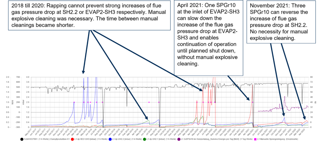
Black: Steam flow
Red: Flue gas pressure drop VD2-ÜH3
Blu: Flue gas pressure drop ÜH2.2
Green: Flue gas pressure drop ÜH2.1
Purple: Sum of Converted Energy/day of three SPGr10 in horizontal pass
3x SPGr10 & rapping can reverse the increase of flue gas pressure drop in critical SH bundle
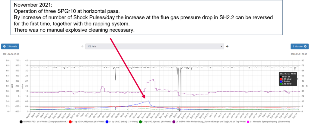
Black: Steam flow
Red: Flue gas pressure drop EVAP2-SH3
Blue: Flue gas pressure drop SH2.2
Green: Flue gas pressure drop SH2.1
Purple: Sum of Converted Energy/day of three SPGr10 in horizontal pass
3x SPGr10 & rapping can keep flue gas pressure drop continously low at line 2
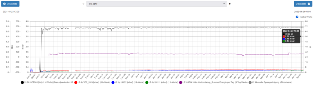
Black: Steam flow
Red: Flue gas pressure drop EVAP2-SH3
Blue: Flue gas pressure drop SH2.2
Green: Flue gas pressure drop SH2.1
Purple: Sum of Converted Energy/day of three SPGr10 in horizontal pass